Ball Valves
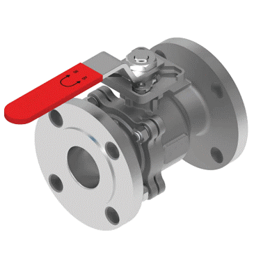
In this type of valve, a rotating ball at its centre, known as a rotary ball, regulates the flow of liquids, vapours and gases. This ball has a hole, known as a bore, at its centre, and a shaft fixed on top of it. The bore is responsible for controlling the passage of substances, while the shaft may be turned using manual or automated levers to open and close the valve. Ball valves are typically compact, affordable and easy to handle. Premium-quality ball valves are also highly durable and resistant to high pressure, volume, and temperatures. Many modern home appliances – including washing machines, dishwashers – as well as specific industries like oil and gas, pharmaceuticals, food and beverage, and automotives make use of ball valves in their equipment.
Brosco’s ball valves are sturdy and durable, ensuring that equipment leveraging these valves can adequately regulate the flow of substances.
- Investment Casting 2PC / 3PC Design
- Sand Casting 2PC / 3PC Design
- Forging 3PC Bolted Design
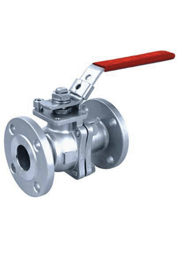
Investment Casting 2PC / 3PC Design
This process is meant to design thin-walled, almost net-shaped castings, after which one does not have to engage in machining.
Product Details
- Manufacturing Range
- Specific Features
1) Size: ¼” NB to 6″ NB
2) Class: 150#
3) Materials: WCB, LCB, CF8,CF8M, CF3, CF3M
Positive Shut-off.
• Compact Design.
• Low-Pressure Drop.
• Longer Life.
• No Lubrication.
• Quick in Action.
• High-Performance
• Stainless steel locking handle.
• Visual Open / Close Indication Simplicity.
• Flanged End, Screwed End BSP/NPT, Butt Weld End.
• Anti-blowout stem
| Sr. No. | Description | Material | Qty. |
|---|---|---|---|
1 | Body | WCB (ASTM A 216 GRADE WCB) | 1 |
CF8 (ASTM A 351 GRADE CF8) | |||
CF8M(ASTM A 351M GRADE CF8M) | |||
2 | F.E. Connector | WCB (ASTM A 216 GRADE WCB) | 1 |
CF8 (ASTM A 351 GRADE CF8) | |||
CF8M (ASTM A 351M GRADE CF8M) | |||
3 | Ball | CF8 (ASTM A 351 GRADE CF8) | 1 |
CF8M (ASTM A 351M GRADE CF8M) | |||
4 | Stem | S.S 304 (ASTM A 276 TYPE 304) | 1 |
S.S 316 (ASTM A 276 TYPE 316) | |||
5 | Ball Seat | PTFE / PEEK / DELRIIN | 2 |
6 | Body Seal | PTFE | 1 |
7 | Stem Seat | PTFE | 4 |
8 | Stem O-Ring | Viton/NBR (ASTM D 3187 GRADE NBR) | 1 |
9 | Stem Lock Nut | S.S 304 (ASTM A 276 TYPE 304) | 1 |
10 | 90� Stopper | M.S. / S.S | 1 |
11 | Handle Bush | S.S. | 1 |
12 | Handle | M.S. / S.S. | 1 |
13 | Handle Nut | (ASTM A 194) | 1 |
14 | Sleeve | Rubber | 1 |
15 | Antistatic Spring | S.S 302(ASTM A 276 TYPE 302) | 2 |
16 | Antistatic Ball | S.S 304 (ASTM A 276 TYPE 304) | 2 |
17 | Fitting Stud | (ASTM A 193) | 4 |
18 | Fitting Nut Washer | (ASTM A 194) | 4 |
Standards :
| 1 | 2 |
|---|---|
Design Standard | BS 5361 / API 6D / ISO17292 |
Inspection & Testing Standard | API 598 / BS 5146 / BS 6755 |
Face to Face | ASME B16.10 |
Flange Connection | ASME B16.5 |
Top Flange | ISO 5211 (Direct Mount) |
2 PC/3 PC Ball Valve Flange End
If a fluid gets contaminated while flowing in its channel, backflow of this fluid can contaminate its source. For this reason, backflow of fluids should be prevented to avoid contamination.
Check valves manufactured by Brosco prevent backflow successfully and are resistant to high pressure and temperatures.
2 PC Ball Valve Flange End
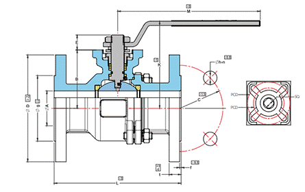
| SIZE | ?A | B | E | L | K | M | ?D | C | ?h | n | t | ?g | f | w (kg) 2PC HANDLE | SQ | PCD | E | w (kg) 2PC ACT |
|---|---|---|---|---|---|---|---|---|---|---|---|---|---|---|---|---|---|---|
�” | 15 | 50 | 15 | 108 | 76 | 145 | 90 | 60.3 | 15.88 | 4 | 10 | 34.9 | 2 | 1.5 | 9 | 42/50 | 9 | 1.4 |
?” | 20 | 55 | 15 | 117 | 82 | 145 | 100 | 69.9 | 15.88 | 4 | 11 | 42.9 | 2 | 1.96 | 9 | 42/50 | 9 | 1.83 |
1″ | 25 | 60.5 | 15 | 127 | 90 | 175 | 110 | 79.4 | 15.88 | 4 | 12 | 50.8 | 2 | 2.63 | 11 | 42/50 | 12 | 2.46 |
1 �” | 32 | 70.5 | 15 | 140 | 100 | 175 | 115 | 88.9 | 15.88 | 4 | 13.2 | 63.5 | 2 | – | 11 | 50/70 | 12 | – |
1 �” | 38 | 73.5 | 21 | 165 | 114 | 200 | 125 | 98.4 | 15.88 | 4 | 15 | 73 | 2 | 5.24 | 14 | 50/70 | 14 | 4.82 |
2″ | 50 | 82 | 21 | 178 | 123 | 200 | 150 | 120.7 | 19.05 | 4 | 16.5 | 92.1 | 2 | 7.83 | 14 | 50/70 | 14 | 7.4 |
2 �” | 63.5 | 100 | 26 | 190 | 146 | 265 | 180 | 139.7 | 19.05 | 4 | 18 | 104.8 | 2 | 12.68 | 17 | 70/102 | 17 | 12 |
3″ | 76 | 110 | 26 | 203 | 156 | 265 | 190 | 152.4 | 19.05 | 4 | 19.5 | 127 | 2 | 16.2 | 17 | 70/102 | 22 | 15.5 |
4″ | 100 | 135 | 28.5 | 229 | 182 | 400 | 230 | 190.5 | 19.05 | 8 | 24.3 | 157.2 | 2 | 27.6 | 22 | 70/102 | 27 | 26.3 |
6″ | 150 | 200 | 28.5 | 394 | 276 | 800 | 280 | 241.3 | 22.2 | 8 | 26 | 215.9 | 2 | 58.5 | 27 | 102/125 | 27 | – |
3 PC Ball Valve Flange End
| SIZE | ?A | B | E | L | K | M | ?D | C | ?h | n | t | ?g | f | w (kg) 3PC HANDLE |
|---|---|---|---|---|---|---|---|---|---|---|---|---|---|---|
�” | 15 | 50 | 15 | 108 | 76 | 145 | 90 | 60.3 | 15.88 | 4 | 10 | 34.9 | 2 | 1.56 |
?” | 20 | 55 | 15 | 117 | 82 | 145 | 100 | 69.9 | 15.88 | 4 | 11 | 42.9 | 2 | 2.1 |
1″ | 25 | 60.5 | 15 | 127 | 90 | 175 | 110 | 79.4 | 15.88 | 4 | 12 | 50.8 | 2 | 2.8 |
1 �” | 32 | 70.5 | 15 | 140 | 100 | 175 | 115 | 88.9 | 15.88 | 4 | 13.2 | 63.5 | 2 | – |
1 �” | 38 | 73.5 | 21 | 165 | 114 | 200 | 125 | 98.4 | 15.88 | 4 | 15 | 73 | 2 | 5.5 |
2″ | 50 | 82 | 21 | 178 | 123 | 200 | 150 | 120.7 | 19.05 | 4 | 16.5 | 92.1 | 2 | 8.1 |
2 �” | 63.5 | 100 | 26 | 190 | 146 | 265 | 180 | 139.7 | 19.05 | 4 | 18 | 104.8 | 2 | 13.17 |
3″ | 76 | 110 | 26 | 203 | 156 | 265 | 190 | 152.4 | 19.05 | 4 | 19.5 | 127 | 2 | 16.72 |
4″ | 100 | 135 | 28.5 | 229 | 182 | 400 | 230 | 190.5 | 19.05 | 8 | 24.3 | 157.2 | 2 | 28.4 |
6″ | 150 | 200 | 28.5 | 394 | 276 | 800 | 280 | 241.3 | 22.2 | 8 | 26 | 215.9 | 2 | 58.5 |
3 PC Ball Valve Screwed End
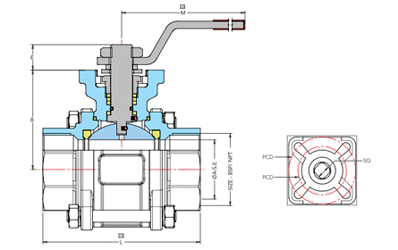
| SIZE | A-S.E | A-T.C | B | E | L | K | M | D | H | G | SQ | PCD | E |
|---|---|---|---|---|---|---|---|---|---|---|---|---|---|
�” | 15 | 15 | 50 | 15 | 65 | 76 | 145 | 34 | 30.45 | 24.55 | 9 | 42/50 | 9 |
?” | 20 | 20 | 55 | 15 | 75 | 82 | 145 | 34 | 30.45 | 24.55 | 9 | 42/50 | 9 |
1″ | 25 | 25 | 60.5 | 15 | 85 | 90 | 175 | 50.5 | 46.45 | 40.55 | 11 | 42/50 | 12 |
1 �” | 32 | 32 | 70.5 | 15 | 85 | 100 | 175 | 50.5 | 46.45 | 40.55 | 11 | 50/70 | 12 |
1 � | 38 | 32 | 73.5 | 21 | 120 | 114 | 200 | 50.5 | 46.45 | 40.55 | 14 | 50/70 | 14 |
2″ | 50 | 42.5 | 82 | 21 | 130 | 123 | 200 | 64 | 59.45 | 53.55 | 14 | 50/70 | 14 |
2 �” | 63.5 | 63.5 | 100 | 26 | 165 | 146 | 265 | 91 | 86.45 | 80.55 | 17 | 70/102 | 17 |
3″ | 76 | 76 | 110 | 26 | 185 | 156 | 265 | 106 | 99.95 | 94.05 | 17 | 70/.102 | 27 |
4″ | 100 | 100 | 135 | 28.5 | 230 | 182 | 400 | 119 | 112.95 | 107.05 | 22 | 70/102 | 27 |
Sand Casting 2PC / 3PC Design
We offer sand casting for steel and iron valve castings. This process lends itself to large valve parts.
Product Details
- Manufacturing Range
- Specific Features
1) Size: 2″ NB to 12″ NB
2) Class: 150#, 300#, 600#
3) Materials: WCB, LCB, CF8,CF8M, CF3, CF3M
• Positive Shut-off.
• Compact Design.
• Low-Pressure Drop.
• Longer Life.
• No Lubrication.
• Quick in Action.
• High-Performance
• Stainless steel locking handle.
• Visual Open / Close Indication Simplicity.
• Flanged End, Screwed End BSP/NPT, Butt Weld End.
• Anti-blowout stem
• Floating Ball / Trunnion Mounted Design
Standards :
| 1 | 2 |
|---|---|
Design Standard | BS 5361 / API 6D / ISO 17292 |
Inspection & Testing Standard | API 598 / BS 5146 |
Face to Face | ASME B16.10 |
Flange Connection | ASME B16.5 |
3 PC Ball Valve Flange End
| P. NO. | ITEM . | QTY | MATERIAL |
|---|---|---|---|
1 | END PIECES | 2 | ASTM A 216 Gr. WCB |
C.l. TO IS 210 Gr. FG 220 | |||
AISI 304 OR CF8 | |||
AISI 316 OR CF8M | |||
ASTM A 105 | |||
G.M. | |||
2 | STUD & NUT | Req. | M.S. ASTM A 193 Gr. B7 |
M.S. ASTM A 194 Gr. 2H | |||
AISI 304 | |||
AISI 316 | |||
3 | BODY | 1 | ASTM A 216 Gr. WCB |
C.l. TO IS 210 Gr. FG 220 | |||
AISI 304 OR CF8 | |||
AISI 316 OR CF8M | |||
ASTM A 105 | |||
G.M. | |||
4 | BALL | 1 | AISI 304/AISI 316 |
5 | SEAT | 2 | PTFE OR FILLED TEFLON |
6 | STEM | 1 | AISI 304/AISI 316 |
7 | INTERLOCK NUT | 1 | CARBON STEEL |
AISI 410/304/316 | |||
8 | LEVER | 1 | CARBON STEEL |
AISI 410/304/316 |
| ASA – 150 | |||||||
|---|---|---|---|---|---|---|---|
SIZE NB | A | ?B | C | ?D | E | F | ?G |
15 | 108 | 35 | 11 | 89 | 4 | 60 | 16 |
20 | 118 | 43 | 13 | 98 | 4 | 70 | 16 |
25 | 127 | 51 | 14 | 108 | 4 | 79 | 16 |
40 | 165 | 73 | 14 | 127 | 4 | 98 | 16 |
50 | 178 | 92 | 16 | 152 | 4 | 121 | 19 |
65 | 190 | 105 | 17 | 178 | 4 | 140 | 19 |
80 | 203 | 127 | 19 | 190 | 4 | 152 | 19 |
100 | 229 | 157 | 24 | 229 | 8 | 216 | 19 |
125 | 254 | 186 | 24 | 254 | 8 | 216 | 22 |
150 | 267 | 216 | 25 | 279 | 8 | 241 | 22 |
200 | 292 | 270 | 29 | 343 | 8 | 296 | 22 |
| ASA – 150 | |||||||
|---|---|---|---|---|---|---|---|
SIZE NB | A | ?B | C | ?D | E | F | ?G |
40 | 191 | 73 | 21 | 156 | 4 | 114 | 22 |
50 | 216 | 92 | 22 | 165 | 8 | 127 | 22 |
65 | 241 | 105 | 25 | 190 | 8 | 149 | 22 |
80 | 282 | 127 | 29 | 209 | 8 | 168 | 22 |
100 | 305 | 157 | 32 | 254 | 8 | 200 | 22 |
125 | 381 | 186 | 35 | 279 | 8 | 235 | 22 |
150 | 403 | 216 | 37 | 318 | 12 | 270 | 22 |
200 | 419 | 270 | 41 | 381 | 12 | 330 | 25 |
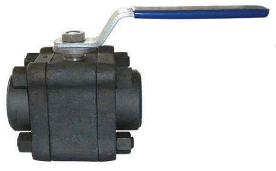
Forging 3PC Bolted Design
In this process, a press, hammer or die is used to hammer and roll the metallic ball valve into its shape. Basically, heated metal is shaped into the required design so that the ball valve can fulfil its intended purpose.
Product Details
- Manufacturing Range
- Specific Features
1) Size: ¼” NB to 2″ NB
2) Class: 800#, 1500#
3) Materials: A105, LF2, F5, F11,A182 (F304 / F316)
- Full port or reduce port.
- Mirror finished SS balls.
- Wide range of seals.
- Anti-blowout stems
- Socket Weld End, Screwed End BSP/NPT, Butt Weld End.
Standards :
| 1 | 2 |
|---|---|
Design Standard | BS 5351 / BS EN 17292 |
Inspection & Testing Standard | API 598 / BS EN 12266-1 |
Socket Weld End | ASME B16.11 |
Screwed End | ASME B20.1 |
Butt Weld Connection | ASME B16.25 |
Pressure Temperature Rating | ASME B16.34 |
3 PC Ball Valve Flange End
| Sr. No. | Description | Qty. | Material |
|---|---|---|---|
1 | BODY | 1 | ASTM A 216 Gr. WCB |
C.l. TO IS 210 Gr. FG 220 | |||
AISI 304 OR CF8 (I.C.) | |||
AISI 316 OR CF8M (I.C.) | |||
ASTM A 105 | |||
2 | BODY CONNECTOR | 1 | ASTM A 216 Gr. WCB |
C.I. TO IS 210 Gr. FG 220 | |||
AISI 304 OR CF8 (I.C.) | |||
AISI 316 OR CF8M (I.C.) | |||
ASTM A 105 | |||
3 | BALL | 1 | AISI 304/AISI 316 |
4 | STEM | 1 | AISI 304/AISI 316 |
5 | GLAND NUT | 1 | AISI 304/AISI 316 |
6 | GLAND BUSH | 1 | AISI 304/AISI 316 |
7 | SEAT RING | 2 | PTFE OR FILLED PTFE |
8 | BODY SEALENT RING | 2 | PTFE OR FILLED PTFE |
9 | STEM SEAL | 2 | PTFE OR FILLED PTFE |
10 | STOPPER | 1 | C.S./S.S.304/S.S.316 |
11 | STUD & NUT | 4 | C.S./S.S.304/S.S.316 |
12 | LOCK NUT | 1 | AISI 304/AISI 316 |
13 | LEVER | 1 | C.S./S.S.304/S.S.316 |
| ASA – 150 | |||||||
|---|---|---|---|---|---|---|---|
SIZE NB | A | ?B | L | BSP/BSPT NPT | F | G | H |
15 | 90 | 13 | 150 | 1/2″ | 21.8 | 29 | 12.7 |
20 | 95 | 19 | 150 | 3/4″ | 27.3 | 35 | 19 |
25 | 100 | 25 | 150 | 1″ | 34.1 | 43 | 22 |
32 | 110 | 32 | 160 | 1.1/4″ | 43 | 54 | 22 |
40 | 120 | 38 | 160 | 1.1/2″ | 49 | 58 | 22 |
50 | 130 | 50 | 160 | 2″ | 61.3 | 71 | 23 |
| ASA – 800 | |||||||
|---|---|---|---|---|---|---|---|
SIZE NB | A | ?B | L | BSP/BSPT NPT | F | G | H |
15 | 68 | 12 | 115 | 1/2″ | 21.8 | 29 | 12.7 |
20 | 79 | 16 | 122 | 3/4″ | 27.3 | 35 | 19 |
25 | 95 | 18 | 153 | 1″ | 34.1 | 43 | 22 |
32 | 107 | 24 | 178 | 1.1/4″ | 43 | 54 | 22 |
40 | 117 | 32 | 178 | 1.1/2″ | 49 | 58 | 22 |
50 | 130 | 37 | 178 | 2″ | 61.3 | 71 | 23 |
OUR CLIENTS
Customers Have and Things We Do Every Day to Meet Those Needs A positive introduction. We work hard to provide the very best on-boarding experience possible.


